Research Article | | Peer-Reviewed

Research on Static Mechanical Properties of Gravity-Type Deep-Water Net Cage Floating Collar System Under Different Spacing Between Connecting Frames

Received: 10 August 2026     Accepted: 20 August 2026     Published: 9 September 2026
Views:       Downloads:
Abstract

As global demand for seafood escalates, offshore marine aquaculture has increasingly expanded into open-ocean environments. Gravity-type deep-water net cages are widely used in marine aquaculture due to their cost-effectiveness and resistance to wave action. The floating collar system, typically constructed from high-density polyethylene (HDPE) pipes, serves as the primary load-bearing component and plays a crucial role in maintaining overall structural safety and buoyancy, with the connecting frames arrangement being particularly crucial. However, there is no standardized spacing for connecting frames, making research on their mechanical influence essential for design optimization. This study systematically evaluated the static performance of net cages under varying frame spacing and cage sizes using numerical simulation software ANSYS. Results show that under tensile loading, maximum stress increases at an accelerating rate with larger frame spacing. In contrast, under bending and torsion, stress initially rises before declining. Equivalent stiffness consistently declines with greater spacing, though the rate varies by loading condition. Furthermore, enlarging the cage circumference consistently decreases equivalent stiffness across all cases and generally elevates maximum stress, particularly under tensile and bending loads. Notably, cage circumference exerts a more pronounced impact on mechanical performance than frame spacing, particularly in bending scenarios where structural deformation is most critical. Compared to torsion, bending loads result in higher maximum stress and lower equivalent stiffness, indicating that the structure is highly vulnerable to bending-induced deformation and requires additional reinforcement. These findings can offer practical guidance for optimizing the connecting frame arrangement and improving the structural design of floating collar systems in gravity-type deep-water net cages.

Published in Applied Engineering (Volume 10, Issue 2)
DOI 10.11648/j.ae.20261002.11
Page(s) 17-30
Creative Commons

This is an Open Access article, distributed under the terms of the Creative Commons Attribution 4.0 International License (http://creativecommons.org/licenses/by/4.0/), which permits unrestricted use, distribution and reproduction in any medium or format, provided the original work is properly cited.

Copyright

Copyright © The Author(s), 2026. Published by Science Publishing Group

Keywords

Net Cage, Floating Collar System, Connecting Frame, Numerical Simulation, Equivalent Stiffness

1. Introduction
With the rapid growth of the global population and the surging demand for food, particularly high-quality proteins, the limitations of traditional terrestrial farming methods are becoming increasingly evident . Aquaculture has gradually become an important solution to address the challenges of food supply and the provision of high-quality protein, due to its significant development potential. Among aquaculture systems, net cages serve as essential infrastructure for mariculture development. Notably, high-density polyethylene (HDPE) gravity-type deep-water net cages have gained widespread adoption due to their superior wind and wave resistance and cost-effectiveness .
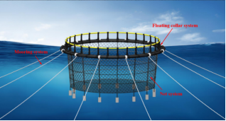
The composition of the HDPE gravity-type deep-water net cage is shown in Figure 1, which mainly includes a floating collar system, a net system, and a mooring system. The floating collar system provides buoyancy and support for the aquaculture net cage to ensure the safety of the main body in a harsh environment. The floating collar system mainly consists of inner and outer floating collars and connecting frames, in which the connecting frames connect the inner and outer floating collars into a whole to ensure stability by improving the overall stiffness of the floating collar system; therefore, the number of connecting frames is crucial for the design of the floating collar system.
Figure 1. Diagram of the gravity-type deep-water net cage.
In recent years, extensive research has been conducted on the mechanical properties and hydrodynamic characteristics of floating collar structures in aquaculture net cages through both numerical simulations and physical model tests. In terms of modeling approaches, Wang et al. and Fredriksson et al. advanced modeling techniques from the perspectives of reliability design and HDPE material properties, respectively, while Dong et al. conducted systematic research on the mechanical behavior of floating collars. Zhao et al. further systematically compared the applicability of different modeling methods.
For research on hydrodynamics and structural performance, early foundational work by Lee et al. established a coupled dynamic model. Meanwhile, Liu et al. investigated reinforced structures, and Fu et al. analyzed wave responses—collectively deepening the understanding of environmental load mechanisms of the gravity-type net cage floating collar system. Subsequent studies further expanded this knowledge, including environmental load assessments by Syalsabila et al. and Syarifudin et al. , dynamic response simulations by Pang et al. , numerical accuracy improvements by Park et al. , and investigations into hydrodynamic characteristics by Xu et al. . Qin et al. examined the dynamic response of gravity-type net cages under extreme conditions. Notably, Huang et al. made breakthroughs in floating collar analysis, optimized structural designs, and provided a theoretical basis for safety standards.
Research on fatigue performance has also advanced. Liu et al. developed numerical models and conducted systematic analyses of fatigue characteristics, providing a foundational understanding of structural degradation under cyclic loading. Complementing this work, Bai et al. employed probabilistic and deterministic approaches to assess fatigue life, offering critical insights into long-term structural reliability. Further contributions include Zhang et al.'s investigation into storm load effects, which expanded the understanding of extreme environmental impacts on fatigue behavior.
Gravity-type deep-water net cages are widely adopted in marine aquaculture, with the floating collar system serving as a critical load-bearing structure. While numerous studies have investigated the hydrodynamic behavior and mechanical performance of floating collars under environmental loads, most focus on external forces such as waves and currents. However, limited attention has been paid to how structural parameters, particularly the arrangement and spacing of connecting frames, affect the overall static performance and stiffness of the floating collar system.
This study systematically evaluates the static mechanical behavior of gravity-type deep-water net cage floating collar systems with varying cage sizes and connecting frame spacing. Using ANSYS simulations, the floating collar is analyzed under tensile, bending, and torsional loading conditions to evaluate the effects of frame spacing on stress distribution and equivalent stiffness. The results reveal distinct mechanical trends under different loading scenarios and highlight the greater influence of cage circumference compared to frame spacing. This study provides quantitative insights and design references for optimizing the number and placement of connecting frames to enhance the safety and durability of net cage structures.
2. Modelling of the Net Cage Floating Collar System
2.1. Parameters of the Floating Collar System
This study focuses on the widely used double floating collar circular gravity-type deep-water net cage. Since the handrail frames in the floating collar system are not load-bearing components, the analysis primarily centers on the inner, outer floating collars and connecting frame components. The floating collar components are made of high-density polyethylene, with their geometry and material parameters detailed in Table 1. To investigate the effects of different cage sizes and connecting frame spacing on the forces acting on the floating collar, in this study, static mechanical calculations were carried out to analyze structural response characteristics. The analysis covers cages with circumference ranging from 60 m to 150 m and the connecting frame spacing ranging from 0.5 m to 5 m.
Table 1. Main parameters of floating collar simulation.

Parameters

Value

Outer diameter of inner and outer floating collar

450 mm

Thickness of inner and outer floating collar

35 mm

Center distance between inner and outer floating collar

800 mm

Outer diameter of connecting frame

450 mm

Thickness of connecting frame

35 mm

Density

1,000 kg/m3

Modulus of elasticity

950 MPa

Poisson's ratio

0.42

Yield strength

24.1 MPa

2.2. Modelling of Floating Collar Systems
In this study, the finite element software ANSYS/Mechanical is used. The components of the floating collar structure are regarded as PIPE elements in the simulation. Specifically, the PIPE20 element is a three-dimensional plastic straight pipe element based on beam theory, whose geometrical characteristics are defined by two nodes in linear or curved form. Each node contains six degrees of freedom and exhibits tensile, bending, and torsion properties, while also accounting for material properties such as plasticity, creep, and expansion. In addition, the actual structure of the connecting frames, which serve as the connecting part of the inner and outer floating collar, is relatively complex. However, considering the small center distance between the inner and outer collars, the connecting frames are simplified to be the same scale pipe as the inner and outer floating collars in the simulation.
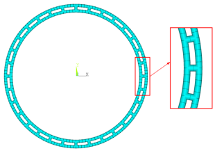
The model adopts a top-down modelling method to construct the floating collar structure. In terms of cell property setting, an autonomously controlled meshing method is adopted to effectively manage mesh size, element count, and program efficiency while ensuring computational accuracy. To enhance computational efficiency when handling variable parameters such as net cage sizes and connecting frame spacing, a specialized modelling and calculation program was developed using ANSYS APDL language. Figure 2 illustrates a finite element model of a floating collar with a circumference of 60 m and connecting frame spacing of 2 m. It should be noted that to ensure that the loading points and restraining points are located on the connecting frames, the number of connecting frames should be determined as a multiple of 4. The specific circumference of the net cage and the spacing of connecting frames are detailed in Table 2.
Figure 2. Finite element model of floating collar.
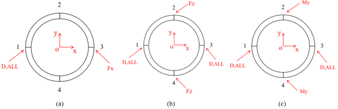
Table 2. Selection of parameters for net cages connecting frame.

Connecting frames spacing (m)

Circumference (m)

Number of connecting frames

Circumference (m)

Number of connecting frames

Circumference (m)

Number of connecting frames

Circumference (m)

Number of connecting frames

0.5

60

120

90

180

120

240

150

300

1

60

60

90

92

120

120

150

152

1.5

60

40

90

60

120

80

150

100

2

60

32

90

44

120

60

150

76

2.5

60

24

90

36

120

48

150

60

3

60

20

90

32

120

40

150

52

3.5

60

16

90

28

120

36

150

44

4

60

/

90

24

120

32

150

36

4.5

60

/

90

20

120

28

150

32

5

60

/

90

16

120

24

150

28

2.3. Loading Conditions
In this study, the structural response of the net cage floating collar system is analyzed through static calculations, focusing on load types under tensile, bending, and torsion conditions. For the tensile conditions, the left node at position 1 is fully restrained (D, ALL), and a series of loads are incrementally applied in the Fx (+) direction at the node 3, increasing by 2,000 N up to 20,000 N. For the bending conditions, the floating collar is fully restrained (D, ALL) at the left and right position nodes 1 and 3, and a series of loads are applied with increments of 2,000 N up to 20,000 N in the Fz (+) direction at the upper and lower position nodes 2 and 4. Under the torsion conditions, the left and right nodes of node 1 and node 3 are fully restrained (D, ALL), and a series of torques are applied incrementally in the My (-) direction at node 2 and My (+) direction at node 4, with increments of 2,000 N·m up to 20,000 N·m. The restraint diagrams of the net cage are shown in Figure 3.
Figure 3. Restraint diagrams of loading conditions. (a) tensile conditions; (b) bending conditions; (c) torsion conditions.
3. Results and Discussion
3.1. Determination of Floating Collar Strength and Stiffness
In this study, the strength and stiffness of the floating collar are analyzed and evaluated by extracting the maximum stress, maximum displacement, and deformation of the floating collar of the net cage under different working conditions. In ANSYS post-processing, the Von Mises stress criterion is used to calculate the maximum stresses and displacements, which can be used to determine the fatigue, damage, and strength of the floating collar system.
Based on the loads acting on the floating collar system and the maximum displacement in the post-processing, the equivalent stiffness of the net cage floating collar can be calculated by Equation (1):
K=F/δ(1)
Where K is the equivalent stiffness, F is the constant force/moment acting on the structure, and δ is the deformation produced by the force.
In the ANSYS post-processing module, the stress distribution, displacement, and deformation on the floating collar are analyzed, which serves as the basis for evaluating the performance of the floating collar.
3.2. Tensile Condition
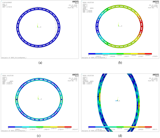
Figure 4. Contour plot of finite element results under tensile condition. (a) Overall deformation diagram; (b) Displacement contour; (c) Stress contour; (d) Strain contour.

Download: Download full-size image

Figure 4 shows the contour plot of a floating collar with a circumference of 60 m and a connecting frame spacing of 2.5 m under a tension load of 10,000 N. As shown in Figure 4(a) and Figure 4(b), the floating collar undergoes deformation and displacement in the X and Y directions under tension, with the maximum displacement appearing at the loading position on the far right of the floating collar, amounting to 0.270678 m. Figure 4(c) and Figure 4(d) show that stress concentration in the floating collar under the tensile conditions is mainly distributed in the restrained and loading positions, with the maximum stress occurring at the outer floating collar at the loading position, reaching a value of 3.51E6 Pa. This aligns with the fatigue-critical zones identified by Zhang et al. under storm wave conditions, highlighting the need for reinforced designs at these locations. The results for the tensile condition calculations of net cages with circumferences of 60 m, 90 m, 120 m, and 150 m (C60, C90, C120, and C150) under different connecting frame spacing are shown in Figure 5.
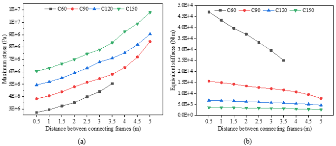
Figure 5. Comparative analysis of mechanical response under tensile conditions (Fx = 10 kN). (a) Maximum Von Mises stress comparison; (b) Equivalent stiffness comparison.
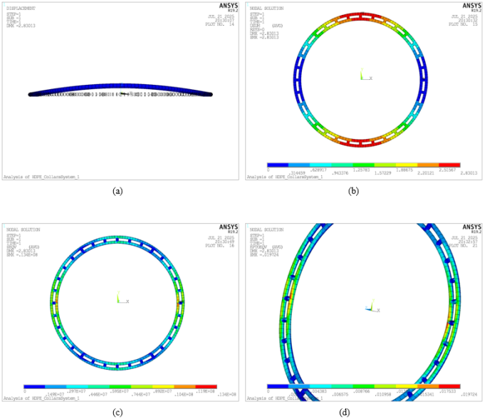
Figure 5 presents the curves depicting maximum stress and equivalent stiffness for floating collar structures of different sizes under tensile conditions as the connecting frames spacing varies. As illustrated, net cages with larger circumferences experience higher stress and lower equivalent stiffness, whereas those with smaller circumferences show lower stress and higher equivalent stiffness. For cages with the same circumference, the maximum stress consistently rises with increased spacing of connecting frames, while the equivalent stiffness decreases. Additionally, under the same connecting frame spacing, the maximum stress increases with an increase in circumference, and the equivalent stiffness decreases as the circumference grows.
Table 3. Ratio of incremental change of different connecting frames spacing for different sizes of mesh cages under tensile conditions.

C60

C90

C120

C150

Spacing changes

Stress increment ratio

Equivalent stiffness increment ratio

Stress increment ratio

Equivalent stiffness increment ratio

Stress increment ratio

Equivalent stiffness increment ratio

Stress increment ratio

Equivalent stiffness increment ratio

0.5 - 1

8.27%

-8.03%

6.03%

-4.05%

5.34%

-2.56%

4.13%

-1.66%

1 - 1.5

10.48%

-8.48%

8.18%

-4.87%

5.77%

-2.91%

5.56%

-2.00%

1.5 - 2

8.00%

-6.76%

9.20%

-5.76%

7.27%

-3.28%

5.26%

-2.11%

2 - 2.5

13.52%

-9.95%

7.50%

-5.09%

6.78%

-3.68%

6.43%

-2.66%

2.5 - 3

10.42%

-11.33%

5.83%

-3.94%

7.94%

-4.11%

4.70%

-2.23%

3 - 3.5

14.82%

-15.12%

6.42%

-5.24%

4.41%

-3.07%

7.05%

-3.28%

3.5 - 4

/

/

9.48%

-7.48%

6.34%

-4.07%

10.78%

-5.57%

4 - 4.5

/

/

13.39%

-11.29%

8.61%

-5.72%

7.03%

-4.43%

4.5 - 5

/

/

17.36%

-18.36%

10.37%

-8.44%

9.09%

-6.37%

Table 4. Mean data of different net cage sizes in the spacing of 0.5 m - 3.5 m connecting frames for tensile conditions.

Circumference (m)

Average stress (Pa)

Average equivalent stiffness (N/m)

Stress increment ratio

Equivalent stiffness increment ratio

C60

3.69E+06

36,392.25

/

/

C90

4.78E+06

13,517.68

29.45%

-62.86%

C120

5.96E+06

6,277.26

24.74%

-53.56%

C150

7.09E+06

3,395.28

18.84%

-45.91%

Table 3 shows the stress and equivalent stiffness percentage changes in different-sized net cages under tensile conditions due to variations in the spacing between connection frames. From Table 3, it is evident that the growth rate of the maximum stress curve for net cages of the same size increases with the increase in connecting frame spacing. In the case of a net cage with a circumference of 120 m, when the connecting frame spacing increases from 0.5 m to 1 m, the maximum stress increases by 5.34%, and the equivalent stiffness decreases by 2.56%. When the spacing of connecting frames increases from 4.5 m to 5 m, the maximum stress increases by 10.37%, and the equivalent stiffness decreases by 8.44%. The rate at which equivalent stiffness declines generally accelerates with larger connecting frame spacing. These results indicate that, under tensile conditions for net cages with the same perimeter, the maximum stress in the floating collar escalates with increased connecting frame spacing, whereas the equivalent stiffness diminishes. Consequently, it is demonstrated that under tensile conditions, for cages of the same size, larger spacing between connecting frames has a more pronounced impact on the overall performance of the cage compared to smaller spacing.
Table 4 shows the average stresses and average equivalent stiffnesses for different-sized cages with the connecting frame spacing ranging from 0.5 m to 3.5 m. By comparing the percentage increments in connecting frame spacing detailed in Table 3 and Table 4, it can be observed that the average stress for the net cage with a circumference of 90 meters increases by 29.45% compared to the net cage with a circumference of 60 meters, while the equivalent stiffness decreased by 62.86%. This magnitude of change is significantly greater than the incremental changes caused by variations in connecting frame spacing for the cage with a circumference of 60 m. Furthermore, as the circumference increases, the incremental changes in average stress and average equivalent stiffness decrease gradually. It is demonstrated that changes in circumference have a greater impact on the overall performance of the net cage than changes in the spacing between connecting frames.
Based on the charts above, the following conclusions can be drawn: in the case of the same circumference, with the increase of connecting frame spacing, the number of connecting frames decreases, which leads to the weakening of the binding force between adjacent connecting frame connectors, which is reflected in the increase in stress and displacement under the same loading conditions. For the same spacing between connecting frames, as the circumference increases, the number of connecting frames increases. Theoretically, the equivalent stiffness should increase with more constraints. However, the increase in the circumference of the net cage weakens the binding force to a degree that surpasses the strengthening effect of additional connecting frames, which is reflected in higher stresses and larger displacement with larger circumferences under the same load conditions. Therefore, it is evident that changes in the circumference of the net cage have a more significant impact on its overall performance than variations in the spacing between connecting frames under tensile conditions.
3.3. Bending Condition
As shown in Figure 6, the finite element result contour plot depicts the behavior of a floating collar with a circumference of 60 m and a connecting frame spacing of 2 m under a bending condition with a force of 10,000 N. From Figure 6(a) and Figure 6(b), it can be observed that the deformation and displacement of the floating collar occur in the Z-direction under bending conditions. The maximum displacement occurs at the point where the load is applied, with a value of 2.83013 m. Figure 6(c) and Figure 6(d) reveal that the stress concentration in the floating collar primarily occurs in the restrained and loaded region, and the maximum stress occurs on the floating collar in the restrained region, with a value of 1.34×10⁷ Pa. These results are consistent with the findings of Pang et al. , whose dynamic simulations of a novel single-point mooring system likewise demonstrated significant stress concentrations at key structural connections under irregular wave conditions. The bending condition calculation results for the floating collar with circumferences of 60 m, 90 m, 120 m, and 150 m, with different spacing between connecting frames, are presented in Figure 7.
Figure 6. Contour plot of finite element results under bending condition. (a) Overall deformation diagram; (b) Displacement contour; (c) Stress contour; (d) Strain contour.
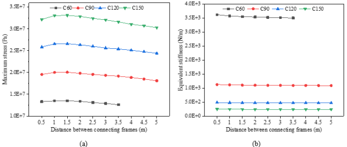
Figure 7. Comparative analysis of mechanical response under bending conditions (Fz = 10 kN). (a) Maximum Von Mises stress comparison; (b) Equivalent stiffness comparison.
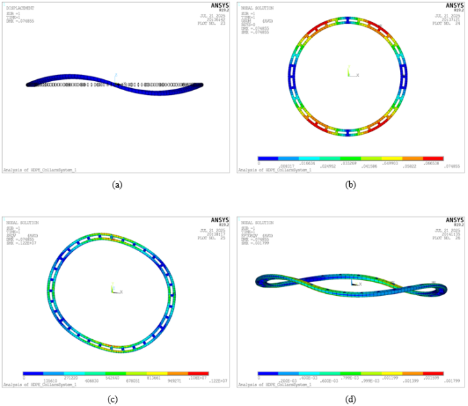
Figure 7 illustrates the maximum stress and equivalent stiffness of the floating collar with different sizes under bending conditions as the connecting frame’s spacing varies. From Figure 7, it is evident that net cages with larger circumferences experience greater stress and lower equivalent stiffness, whereas net cages with smaller circumferences exhibit smaller stress and higher equivalent stiffness. For floating collars with the same circumference, the maximum stress shows a trend of increasing and then decreasing as the spacing of connecting frames widens, while the equivalent stiffness declines with increased connecting frame spacing. As the connecting frame’s spacing decreases, the number of connecting frames increases, resulting in greater overall stiffness and stronger constraint effects for the net cage, which reduces its flexibility and leads to smaller stress effects. Conversely, as the spacing increases, the flexibility gradually restores, leading to increased stress. When the number of connecting frames falls below a certain spacing threshold, the characteristics of the HDPE material lead to excessive flexibility and insufficient stiffness, causing the net cage to become overly flexible and lacking in rigidity. When the stress is applied to a specific location of the net cage, the structure absorbs the load through the overall deformation, resulting in increased displacement of the net cage and decreased stress at the loading position. It demonstrates that under the bending condition, the maximum stress increases and then decreases with the widening of the connecting frame’s spacing, and the rate of decrease gradually accelerates. Meanwhile, the equivalent stiffness decreases as the connecting frames’ spacing increases, while the rate of decrease gradually slows down.
Table 5. Ratio of incremental change in spacing of different connecting frames for different sizes of net cage under bending conditions.

C60

C90

C120

C150

Spacing changes

Stress increment ratio

Equivalent stiffness increment ratio

Stress increment ratio

Equivalent stiffness increment ratio

Stress increment ratio

Equivalent stiffness increment ratio

Stress increment ratio

Equivalent stiffness increment ratio

0.5 - 1

1.35%

-1.20%

2.43%

-1.17%

2.71%

-1.21%

2.80%

-1.20%

1 - 1.5

0.15%

-0.68%

0.12%

-0.70%

0.19%

-0.66%

0.15%

-0.68%

1.5 - 2

-0.74%

-0.36%

-1.25%

-0.47%

-0.94%

-0.43%

-0.76%

-0.40%

2 - 2.5

-2.24%

-0.44%

-1.26%

-0.28%

-1.33%

-0.30%

-1.37%

-0.31%

2.5 - 3

-1.53%

-0.26%

-1.02%

-0.16%

-1.54%

-0.22%

-1.08%

-0.17%

3 - 3.5

-2.33%

-0.30%

-1.03%

-0.16%

-0.78%

-0.12%

-1.40%

-0.18%

3.5 - 4

/

/

-1.57%

-0.17%

-1.18%

-0.12%

-1.74%

-0.19%

4 - 4.5

/

/

-1.86%

-0.18%

-1.39%

-0.13%

-1.13%

-0.10%

4.5 - 5

/

/

-2.16%

-0.19%

-1.41%

-0.13%

-1.30%

-0.10%

Table 6. Mean data of different net cage sizes in the spacing of 0.5 m - 3.5 m connecting frame for bending conditions.

Circumference (m)

Average stress (Pa)

Average equivalent stiffness (N/m)

Stress increment ratio

Equivalent stiffness increment ratio

C60

1.32E+07

3,541.22

/

/

C90

1.96E+07

1,109.83

48.98%

-68.66%

C120

2.61E+07

481.41

32.64%

-56.62%

C150

3.25E+07

250.68

24.60%

-47.93%

Table 5 shows the impact of the connecting frame’s spacing on stress and stiffness under various circumferences. It can be observed that, for a given circumference, as the connecting frame’s spacing increases, the maximum stress on the floating collar initially increases and then decreases, while the equivalent stiffness continuously decreases. Overall, as the connecting frame’s spacing increases, the rate of maximum stress reduction in the net cage increases, whereas the rate of equivalent stiffness reduction decreases. For the net cage with a circumference of 120 m, when the connecting frame spacing increases from 1.5 m to 2 m, the maximum stress decreases by 0.94% and the equivalent stiffness decreases by 0.43%. As the connecting frame spacing increases from 4.5 m to 5 m, the maximum stress decreases by 1.41% and the equivalent stiffness decreases by 0.13%. A comparative analysis of Table 5 and Table 6 reveals that changes in connecting frame spacing have a smaller impact on the overall performance compared to changes in circumference. This indicates that, under bending conditions, variations in circumference have a more significant effect on the overall performance of the floating collar system.
3.4. Torsion Condition
Figure 8. Contour plot of finite element results under torsion conditions. (a) Overall deformation diagram; (b) Displacement contour; (c) Stress contour; (d) Strain contour.
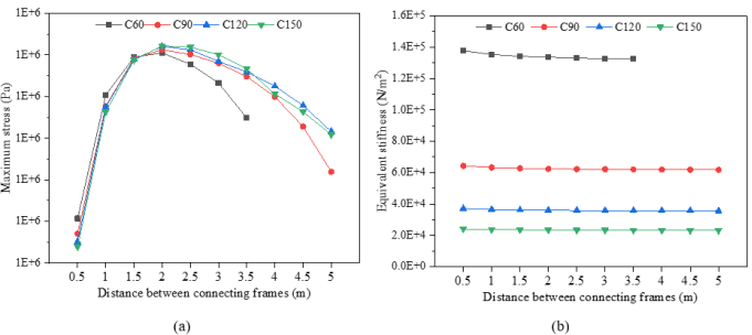
Figure 8 presents the results of a floating collar structure with a circumference of 60 m and a connecting frame spacing of 2 m under torsion conditions. From Figure 8(a) and Figure 8(b), it is evident that the floating collar undergoes deformation and displacement in the X, Y, and Z directions, exhibiting a bow-shaped torsional form. The maximum displacement occurs in the region adjacent to the loading position, with a value of 0.074855 m. Stress concentration occurs in both the restrained and the loading positions, with the maximum stress located at the loading position, with a value of 1.22×10⁶ Pa. The calculation results for net cages with circumferences of 60 m, 90 m, 120 m, and 150 m featuring various connecting frame spacing under torsion conditions are presented in Figure 9.
Figure 9. Comparative analysis of mechanical response under torsion conditions (My = 10 kN•m). (a) Maximum Von Mises stress comparison; (b) Equivalent stiffness comparison.

Figure 9 shows the maximum stress and equivalent stiffness of net cage floating collar structures of various sizes with varying connecting frame spacing. Figure 9 indicates that, at smaller connecting frame spacing, the maximum stress among net cages of different circumferences does not vary significantly. For net cages of the same circumference, the maximum stress increases initially and then decreases as the connecting frame spacing increases. The equivalent stiffness decreases as the connecting frames spacing increases, with smaller-sized net cages exhibiting greater equivalent stiffness, while larger-sized net cages have lower equivalent stiffness.
Table 7. Ratio of incremental change in spacing of different connecting frames for different sizes of net cage under torsion conditions.

C60

C90

C120

C150

Spacing changes

Stress increment ratio

Equivalent stiffness increment ratio

Stress increment ratio

Equivalent stiffness increment ratio

Stress increment ratio

Equivalent stiffness increment ratio

Stress increment ratio

Equivalent stiffness increment ratio

0.5 - 1

2.51%

-1.69%

2.61%

-1.58%

2.76%

-1.59%

2.76%

-1.50%

1 - 1.5

0.75%

-0.92%

0.95%

-0.87%

0.95%

-0.80%

1.03%

-0.82%

1.5 - 2

0.09%

-0.41%

0.17%

-0.54%

0.25%

-0.50%

0.28%

-0.46%

2 - 2.5

-0.22%

-0.38%

-0.09%

-0.28%

-0.07%

-0.32%

-0.03%

-0.34%

2.5 - 3

-0.37%

-0.28%

-0.17%

-0.12%

-0.23%

-0.21%

-0.15%

-0.17%

3 - 3.5

-0.69%

-0.14%

-0.26%

-0.19%

-0.21%

-0.13%

-0.28%

-0.16%

3.5 - 4

/

/

-0.40%

-0.14%

-0.28%

-0.10%

-0.50%

-0.21%

4 - 4.5

/

/

-0.59%

-0.12%

-0.38%

-0.11%

-0.36%

-0.11%

4.5 - 5

/

/

-0.90%

-0.12%

-0.52%

-0.15%

-0.45%

-0.06%

Table 8. Mean data of different net cage sizes in the spacing of 0.5 m - 3.5 m connecting frame for torsion conditions.

Circumference (m)

Average stress (Pa)

Average equivalent stiffness (N/m)

Stress increment ratio

Equivalent stiffness increment ratio

C60

1.21E+06

134,167.27

/

/

C90

1.21E+06

62,713.32

0.13%

-53.26%

C120

1.21E+06

36,182.31

0.01%

-42.31%

C150

1.21E+06

23,520.53

0.01%

-34.99%

Table 7 details the changes in the connecting frame’s spacing across various circumferences. Under the same circumference conditions, the maximum stress of the floating collar shows a trend of increasing and then decreasing with the increase of the connecting frame spacing. From Table 7, as the connecting frames spacing increases, the stress initially increases and then decreases, followed by a negative growth rate with the decline gradually widening. The percentage increment for small-spacing connecting frames is greater than for large-spacing frames. The equivalent stiffness continues to decrease, and the rate of decrease slows as the connecting frame spacing increases. This indicates that within the small-spacing range, changes in connecting frame spacing have a significant effect on the performance of the net cages, while the impact is relatively minor within the large-spacing interval.
Table 8 illustrates the impact of circumference changes on stress and equivalent stiffness. Within the 0.5 m to 3.5 m range of connecting frame spacing, changes in circumference have a negligible effect on stress. For the same spacing between connecting frames, the equivalent stiffness decreases with increased circumference, with the rate of decrease gradually slowing down. For instance, the average maximum stress of the net cage with a circumference of 90 m increases by 0.13% compared to the net cage with a circumference of 60 m, while the average equivalent stiffness decreased by 53.26%. This indicates that, under torsional conditions, changes in circumference have a minimal impact on stress but a significant impact on equivalent stiffness.
4. Conclusions
This study conducted the finite element analysis on net cages of various sizes, considered different spacing between connecting frames, and derived the following conclusions.
1) Net cage circumference has a significantly greater influence on structural performance than the spacing between connecting frames.
2) Under identical loading conditions and cage size, bending loads compared to tensile loads, result in higher maximum stress and lower equivalent stiffness compared to torsion, indicating that the structure is more vulnerable to bending-induced deformation. Therefore, additional reinforcement should be considered to improve bending resistance.
3) For cages with the same size but varying frame spacing, the maximum stress under tensile loading increases with wider spacing, with an accelerating growth rate. Under bending and torsion, maximum stress first increases and then decreases as spacing widens, while equivalent stiffness consistently declines. Notably, the rate of stiffness reduction is most pronounced under bending.
4) For cages of different sizes with the same frame spacing, maximum stress under tensile and bending increases with cage circumference. Under torsion, stress remains relatively stable with smaller spacing but increases with larger circumference when spacing is wider. Equivalent stiffness decreases in all cases with cage circumference enlargement.
In practical engineering applications, both structural strength and equivalent stiffness must be carefully balanced when selecting the connecting frame layout. A layout with narrow spacing and more frames enhances stiffness and limits deformation, but may reduce structural flexibility and wave adaptability. Conversely, a wider spacing may lower stress and improve hydrodynamic compliance but compromise stiffness and increase deformation risks. This study highlights the importance of optimizing frame layout to ensure structural integrity, safety, and operational reliability of gravity-type deep-water net cages under varying marine conditions.
Abbreviations

HDPE

High-density Polyethylene

APDL

ANSYS Parametric Design Language

CAFS

Chinese Academy of Fishery Sciences

C60

Net Cage With a Circumference of 60 m

C90

Net Cage With a Circumference of 90 m

C120

Net Cage With a Circumference of 120 m

C150

Net Cage With a Circumference of 150 m

Author Contributions
Zhiqiang Wang: Conceptualization, Methodology, Software, Writing – original draft
Jingfu Peng: Data curation, Formal Analysis, Validation
Guoliang Pang: Funding acquisition, Supervision, Writing – review & editing
Funding
This work is supported by the Guangdong Provincial Modern Marine Ranch Core Equipment and Technological Innovation Platform Project (No. GPCGD252200FG182F), Project of Innovation Team Construction of Guangdong Agriculture Research System (No. 2024CXTD02), the National Natural Science Foundation of China (No. 32403089), and the Central Public-interest Scientific Institution Basal Research Fund, CAFS (No. 2023TD97).
Data Availability Statement
The data supporting the outcome of this research work has been reported in this manuscript.
Conflicts of Interest
The authors declare no conflicts of interest.
References
[1] Naylor, R. L., Hardy, R. W., Buschmann, A. H., et al. A 20-year retrospective review of global aquaculture. Nature. 2021, 591, 551–563.
[2] FAO. The State of World Fisheries and Aquaculture 2020. Rome, Italy: FAO; 2020.
[3] Yu, J., Liu, J. Policies in the development of offshore cage aquaculture in China: evolution, performance, and prospects. Reviews in Fisheries Science & Aquaculture. 2023, 31, 216–232.
[4] Cheng, H., Li, L., Ong, M. C. Comparative study of five commonly used gravity type fish cages under pure current conditions. Ocean Engineering. 2022, 250, 110977.
[5] Liu, S., Li, G., Liu, H., et al. Current development status of aquaculture equipment in China. Journal of Fisheries of China. 2023, 47(11), 119615.
[6] Wang, C., Ma, M., Chu, Y., et al. Developments in modelling techniques for reliability design of aquaculture cages: A review. Journal of Marine Science and Engineering. 2024, 12(1), 103.
[7] Fredriksson, D. W., DeCew, J., Tsukrov, I. Development of structural modelling techniques for evaluating HDPE plastic net pens used in marine aquaculture. Ocean Engineering. 2007, 34(16), 2124–2137.
[8] Dong, G., Zheng, Y., Gui, F., et al. Research on the float collar of a gravity fish cage. Engineering Applications of Computational Fluid Mechanics. 2009, 3, 430–444.
[9] Zhao, Y., Bai, X., Dong, G., et al. Numerical analysis of the elastic response of a floating collar in waves. Ocean Engineering. 2015, 95, 175–182.
[10] Zhao, Y., Wang, X., DeCew, J., et al. Comparative study of two approaches to model the offshore fish cages. China Ocean Engineering. 2015, 29, 459–472.
[11] Zhao, Y., Bai, X., Dong, G., et al. Deformation and stress distribution of floating collar of net cage in steady current. Ships and Offshore Structures. 2019, 14, 371–383.
[12] Lee, C. W., Lee, G. H., Choe, M. Y., et al. Dynamic simulation of the fish cage net and floating collar subjected to currents and waves. In Proceedings of the ISOPE International Ocean and Polar Engineering Conference, Vancouver, Canada, 2008; pp. ISOPE-I-08-325.
[13] Liu, Z. C., Soares, C. G. Experimental and numerical studies on the effect of the reinforced tubes on the drag forces of a gravity cage system. Ocean Engineering. 2024, 311, 118780.
[14] Liu, Z. C., Soares, C. G. Numerical study on the effect of cage reinforcement on the behaviour of the circular gravity cage. In Advances in Maritime Technology and Engineering. Boca Raton, FL, USA: CRC Press; 2024, pp. 541–545.
[15] Fu, S., Moan, T. G. Dynamic analyses of floating fish cage collars in waves. Aquacultural Engineering. 2012, 47, 7–15.
[16] Syalsabila, F., Prastianto, R. W., Hadiwidodo, Y. S., et al. Structural analysis of floating net cage bracket in current and wave. IOP Conf. Ser. Earth Environ. Sci. 2022, 972, 012017.
[17] Syarifudin, M. R., Prastianto, R. W., Hadiwidodo, Y. S., et al. Strength analysis of offshore aquaculture net structure under wave and current loads. IOP Conf. Ser. Earth Environ. Sci. 2022, 972, 012018.
[18] Pang, G., Wan, C., Sui, L., et al. Dynamic response simulation for a novel single-point mooring gravity-type deep-water net cage under irregular wave and current. Applied Sciences. 2025, 15, 1570.
[19] Park, S. B., Lee, J., Lee, C. W. Accuracy improvement of numerical simulation with the determination of drag coefficients of floating collars. Aquacultural Engineering. 2020, 90, 102105.
[20] Xu, T., Hou, H., Dong, G., et al. Structural analysis of float collar for metal fish cage in waves. Turkish Journal of Fisheries and Aquatic Sciences. 2017, 17, 257–268.
[21] Xu, T., Dong, G., Zhao, Y., et al. Hydrodynamic characteristics of floating pipes in random waves. In Proceedings of the ASME 2013 32nd International Conference on Ocean, Offshore and Arctic Engineering, Nantes, France, 2013; V005T06A009.
[22] Qin, H., Yu, S., Li, P. Dynamic response of floating collar and cage under waves and current. Ocean Engineering. 2020, 205, 107330.
[23] Huang, X., Guo, G., Tao, Q., et al. Numerical simulation of deformations and forces of a floating fish cage collar in waves. Aquacultural Engineering. 2016, 74, 111–119.
[24] Huang, X., Guo, G., Tao, Q., et al. Dynamic deformation of the floating collar of a net cage under the combined effect of waves and current. Aquacultural Engineering. 2018, 83, 47–56.
[25] Huang, X., Liu, H., Hu, Y., et al. Deformation simulation and structural improvement design for floating collar of deep-water aquaculture net cage. Transactions of the Chinese Society of Agricultural Engineering. 2018, 34(15), 44–49.
[26] Liu, H., Huang, X., Wang, S., et al. Evaluation of the structural strength and failure for floating collar of a single-point mooring fish cage based on finite element method. Aquacultural Engineering. 2019, 85, 32–48.
[27] Liu, H., Huang, X., Pang, G., et al. Structural mechanical properties of circular fish cages determined by finite element analysis and material test. Ocean Engineering. 2022, 261, 112083.
[28] Bai, X., Zhao, Y., Dong, G., et al. Probabilistic analysis and fatigue life assessment of floating collar of fish cage due to random wave loads. Applied Ocean Research. 2018, 81, 93–105.
[29] Bai, X., Xu, T., Zhao, Y., et al. Fatigue assessment for the floating collar of a fish cage using the deterministic method in waves. Aquacultural Engineering. 2016, 74, 131–142.
[30] Zhang, Y., Guo, H., Liu, S., et al. Fatigue vulnerability of sea cage to storm wave loads. Journal of Marine Science and Technology. 2023, 28, 153–164.
Cite This Article
  • APA Style

    Wang, Z., Peng, J., Pang, G. (2026). Research on Static Mechanical Properties of Gravity-Type Deep-Water Net Cage Floating Collar System Under Different Spacing Between Connecting Frames. Applied Engineering, 10(2), 17-30. https://doi.org/10.11648/j.ae.20261002.11

    Copy | Download

    ACS Style

    Wang, Z.; Peng, J.; Pang, G. Research on Static Mechanical Properties of Gravity-Type Deep-Water Net Cage Floating Collar System Under Different Spacing Between Connecting Frames. Appl. Eng. 2026, 10(2), 17-30. doi: 10.11648/j.ae.20261002.11

    Copy | Download

    AMA Style

    Wang Z, Peng J, Pang G. Research on Static Mechanical Properties of Gravity-Type Deep-Water Net Cage Floating Collar System Under Different Spacing Between Connecting Frames. Appl Eng. 2026;10(2):17-30. doi: 10.11648/j.ae.20261002.11

    Copy | Download

  • @article{10.11648/j.ae.20261002.11,
      author = {Zhiqiang Wang and Jingfu Peng and Guoliang Pang},
      title = {Research on Static Mechanical Properties of Gravity-Type Deep-Water Net Cage Floating Collar System Under Different Spacing Between Connecting Frames},
      journal = {Applied Engineering},
      volume = {10},
      number = {2},
      pages = {17-30},
      doi = {10.11648/j.ae.20261002.11},
      url = {https://doi.org/10.11648/j.ae.20261002.11},
      eprint = {https://article.sciencepublishinggroup.com/pdf/10.11648.j.ae.20261002.11},
      abstract = {As global demand for seafood escalates, offshore marine aquaculture has increasingly expanded into open-ocean environments. Gravity-type deep-water net cages are widely used in marine aquaculture due to their cost-effectiveness and resistance to wave action. The floating collar system, typically constructed from high-density polyethylene (HDPE) pipes, serves as the primary load-bearing component and plays a crucial role in maintaining overall structural safety and buoyancy, with the connecting frames arrangement being particularly crucial. However, there is no standardized spacing for connecting frames, making research on their mechanical influence essential for design optimization. This study systematically evaluated the static performance of net cages under varying frame spacing and cage sizes using numerical simulation software ANSYS. Results show that under tensile loading, maximum stress increases at an accelerating rate with larger frame spacing. In contrast, under bending and torsion, stress initially rises before declining. Equivalent stiffness consistently declines with greater spacing, though the rate varies by loading condition. Furthermore, enlarging the cage circumference consistently decreases equivalent stiffness across all cases and generally elevates maximum stress, particularly under tensile and bending loads. Notably, cage circumference exerts a more pronounced impact on mechanical performance than frame spacing, particularly in bending scenarios where structural deformation is most critical. Compared to torsion, bending loads result in higher maximum stress and lower equivalent stiffness, indicating that the structure is highly vulnerable to bending-induced deformation and requires additional reinforcement. These findings can offer practical guidance for optimizing the connecting frame arrangement and improving the structural design of floating collar systems in gravity-type deep-water net cages.},
     year = {2026}
    }
    

    Copy | Download

  • TY  - JOUR
    T1  - Research on Static Mechanical Properties of Gravity-Type Deep-Water Net Cage Floating Collar System Under Different Spacing Between Connecting Frames
    AU  - Zhiqiang Wang
    AU  - Jingfu Peng
    AU  - Guoliang Pang
    Y1  - 2026/09/09
    PY  - 2026
    N1  - https://doi.org/10.11648/j.ae.20261002.11
    DO  - 10.11648/j.ae.20261002.11
    T2  - Applied Engineering
    JF  - Applied Engineering
    JO  - Applied Engineering
    SP  - 17
    EP  - 30
    PB  - Science Publishing Group
    SN  - 2994-7456
    UR  - https://doi.org/10.11648/j.ae.20261002.11
    AB  - As global demand for seafood escalates, offshore marine aquaculture has increasingly expanded into open-ocean environments. Gravity-type deep-water net cages are widely used in marine aquaculture due to their cost-effectiveness and resistance to wave action. The floating collar system, typically constructed from high-density polyethylene (HDPE) pipes, serves as the primary load-bearing component and plays a crucial role in maintaining overall structural safety and buoyancy, with the connecting frames arrangement being particularly crucial. However, there is no standardized spacing for connecting frames, making research on their mechanical influence essential for design optimization. This study systematically evaluated the static performance of net cages under varying frame spacing and cage sizes using numerical simulation software ANSYS. Results show that under tensile loading, maximum stress increases at an accelerating rate with larger frame spacing. In contrast, under bending and torsion, stress initially rises before declining. Equivalent stiffness consistently declines with greater spacing, though the rate varies by loading condition. Furthermore, enlarging the cage circumference consistently decreases equivalent stiffness across all cases and generally elevates maximum stress, particularly under tensile and bending loads. Notably, cage circumference exerts a more pronounced impact on mechanical performance than frame spacing, particularly in bending scenarios where structural deformation is most critical. Compared to torsion, bending loads result in higher maximum stress and lower equivalent stiffness, indicating that the structure is highly vulnerable to bending-induced deformation and requires additional reinforcement. These findings can offer practical guidance for optimizing the connecting frame arrangement and improving the structural design of floating collar systems in gravity-type deep-water net cages.
    VL  - 10
    IS  - 2
    ER  - 

    Copy | Download

Author Information